Roll Measurements and Tolerances by Application
Roll Measurements and Tolerances by Application
Roll measurements should be taken before, during and after regrinding. The best, most reliable reports are computer plotted graphs. Before-grinding reports give valuable information on paper machine operation in the way of analyzing wear patterns, etc. Intermediate reports give the roll grinder operator important data to adjust for the next grinding pass. Finished roll measurement graphs assist the production personnel in selecting the right rolls for the application, and giving them hard data on the roll grinding operation.
Hardness and Finish
Roll hardness and finish should always be measured.
Table II. Target Hardness and Allowable Deviation.
P&J (1/8 in)
3 – 15 ± 3 Units
16 – 49 ± 4
50 – 60 ± 5
61 – 70 ± 6
71 – 80 ± 7
81 – 90 ± 8
91 – 100 ±9
101 – 150 ± 10
151 – 250 ± 25
Shore A 0 – 100 ± 5
Table III. Median Hardness Tolerance
P&J (1/8 in)
20 3 Units
21 – 60 4
61 – 100 5
101 – 150 7
151 – 200 10
Shore A 0 – 200 4Chilled iron calender rolls are measured by schleroscope. Hardness is measured in three places; approximately 50 mm (2 in) from both ends and the middle of the roll face. Four to five measurements are taken at each place and an average reading is recorded. 68 to 70 Shore C is usually minimum hardness allowed and the readings should be within one unit. 72 – 74 or 76 – 78
Shore C hardnesses are required in some calendering applications.
Hard rubber or resin covered rolls are specified in P&J or Shore D units, e.g. 91 ± 2 Shore D.The Rho-meter is an instrument to measure the hardness of super-calender rolls in units from 0 – 100 known as Rhos. Surface finish is most important because the better the roll surfaces are the smoother the paper surface will be due to replication of the roll surfaces onto the paper in alendering and supercalendering.
Table IV. Finish; Typical Tolerances by Application
Chilled Iron Calender Rolls Ra 0,1 µm (4RMS)(premium)
/ 0,2 µm (8 RMS)(std.)
Synthetic Filled Rolls 0,4 µm (16 RMS)
Cotton or Wool Filled Rolls 0,75 µm (30 RMS)
Top Rock Resin Covered Rolls 0,6-3,0 µm (24-120RMS)(Depends on application)
Rubber Covered Coater or Glue Press Rolls 1,6 µm (64 RMS)
Rubber Covered Press Rolls/Suction Rolls 3,2 µm (128 RMS)
Rubber Covered Breast, Lead and Guide Rolls 6,3 µm (252 RMS)
Concentricity and Roundness
T.I.R. (Total Indicator Reading) and roundness should be measuredin three places; the roll middle and both ends. On accurate applications, long rolls, or if a problem is suspected, five measuring locations are recommended. Take readings over several rotations to eliminate possible inaccuracies due to dirt, grease spots, etc. Take at least eight readings over a 360 rotation.The roundness measurement is more important on surface driven rolls such as intermediate calender positions. If a roll takes load on its journals, such as the bottom roll of a calender, concentricity is more important.
Roundness tolerance is typically from 2 µm (.0001 in) to 5 µm (.0002 in) for chilled iron calender rolls depending on the paper grade. The concentricity tolerance at the ends of a roll is usually double the roundness tolerance. 5 to 10 µm (.0002 to .0004 in) is usually allowable measured at 12 o'clock position of the roll, particularly if the roll is ground supported on its own bearings. If a roll is stored in a stationary position, a permanent sag may develop quickly, and T.I.R. (Total Indicator Reading) in the middle of the roll may alter tenfold by the time the roll is installed back in the paper machine. If a roll cannot be stored rotating slowly continuously, it should be rotated manually 180 every two days.
Profile and Crown
Profile, crown and taper readings should also always be taken and recorded. If accuracy is critical, the measurements should be taken in two center lines, 90 apart. The profile tolerance depends on the roll application and position, the material of the roll, shell or cover (the harder the tighter), and the face length and diameter (the smaller the tighter).
Increased paper quality requirements are tightening the tolerances. For instance, many mills with a then premium ± 5 µm (.0002 in) tolerance for chilled iron calender rolls just five years ago, are targeting for ± 2,5 µm (.0001 in) now.
Table V. Guidelines for straight rolls.
Chilled Iron Calender Rolls ± 2,5 µm (.0001 in)(premium) / ± 5 µm (.0002 in)(std.)
Rubber Covered Press Rolls ± 13 µm (.0005 in)(premium) / ± 25 µm (.001 in)(std.) / + 50 µm/-0 (+.002in/-0) (no concavity allowed)
Breast Rolls ± 60 µm (.0025 in)
Cotton or Wool Filled Rolls ± 13 µm (.0005 in)
Synthetic Filled Rolls ± 9 µm (.00035 in)
Crown tolerance applies to both the total crown in the middle of the roll and the values at each station. Continuous graphs with target crown tolerances calculated automatically makes checking easy. Some tolerances are listed in the following Table VI.
Table VI. Guidelines for Crown Rolls.
Chilled Iron Rolls ± 13 µm (.0005 in)(premium) / ± 25 µm (.001 in)(std.)
Rubber Covered Press Rolls ± 13 µm (.0005 in)(premium) / ± 25 µm (.001 in)(std.)
Top Rock Resin Covered Rolls ± 25 µm (.001 in/200 in Face)
± 38 µm (.0015 in/300 in Face)
± 50 µm (.002 in/400 in Face)
Granite Rolls ± 35 µm (.0015 in)
Long Nip Press Rolls ± 50 µm (.002 in)
The station-to-station tolerance is used particularly by roll manufactures to avoid sharp changes in roll profile, within profile or crown tolerance. Table VII offers some guidelines for station-to-station tolerances.
Table VII. Station-to-Station Tolerances.
Straight Chilled Iron Calender Rolls ± 2 µm (.00008 in)(premium) / ± 4 µm (.00015 in)(std.)
Crown Chilled Iron Calender Rolls ± 4 µm (.00015 in)(premium) / ± 8 µm (.0003 in)(std.)
Rubber Covered Press Rolls ± 10 µm (.0004 in)(premium) / ± 20 µm (.0008 in)(std.)
Top Rock Resin Covered Rolls ± 13 µm (.00025 in)
There sometimes are circumferential errors within roundness or concentricity tolerances, too. Flat spots or corrugations may have been induced on the roll either by a roll grinder or a paper machine. The following are some examples.
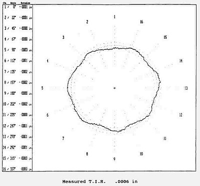
Fig. 7. Worn bottom roll of a supercalender caused excess vibration and the supercalender could not be run at full speed.
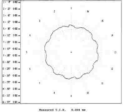
Fig. 8. Corrugations within the tolerances; caused by a roll grinder.
Allowable tolerance for the taper error is usually 50 µm (.002") to 25 µm (.001") or less depending on application and roll size.
Temperature
Higher operating temperatures in some roll applications result in special requirements for roll grinding and measurement, since roll grinding should be performed at or near operating temperature for the best results. For example, higher press section temperatures have resulted in uneven thermal expansion of granite rolls causing operating problems. Now, the granite rolls have to be ground in elevated temperatures to achieve the tolerances at operating temperature.
In general, the temperature tolerance should be 0,1C (.2F) for both the roll and the measurement equipment. Also the roll grinder bed and ways should be at a uniform temperature.
Temperature variations across the roll face have significant effect on roll grinding and measuring. For instance, a difference of 1C (1.8F) on a 1000 mm (40") diameter roll creates a difference of 0,01 mm (.0004") on the diameter. Temperature variations may result in from ambient air temperature differences such as draft through an open doorway, or from the roll grinding operation itself. If a roll is supported from its shoulders, near the ends of the roll face, the heat from friction causes the roll body to increase in diameter. The roll is ground straight at the existing surface temperature, but after it cools off uniformly, the ends of the roll face are tapered down significantly. If temperature differences are suspected, a roll should be let to stabilize in even temperature for up to 24 hours and measured then.